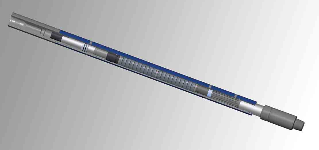
Shock Sub
Impact and vibration reduction tool


The Shock Sub impact and vibration reduction tool is a drillstring component that absorbs and dampens the variable axial dynamic loads produced by the drill bit during routine drilling and milling operations. It is most beneficial when drilling in hard rock, broken formations, and intermittent hard and soft streaks. Reducing the impact loads helps to increase ROP; improve borehole quality; and extend the life of the cutting structure, bearings, connections, and surface equipment—all translating to a lower cost of drilling per foot.
Durable construction for the demands of modern drilling
Advances in drilling technology have necessitated the redesign of shock tools to account for new parameters:
- Increased hole deviation means that the weight required to activate the previous generation of shock tools is simply not available at the bit.
- Drilling motors and MWD tools require drillstring components with a larger ID.
With enhanced reliability, better fatigue and corrosion resistance, large ID, significant reduction of vibrations, and the ability to operate with low or high weight on bit (WOB), the Shock Sub impact and vibration reduction tool meets the challenges of modern drilling. It is made of high-quality, hardened steel. Seals isolate internal components from the drilling fluid and can withstand temperatures up to 400 degF.
Absorbs shock continuously
The Shock Sub impact and vibration reduction tool does not need to be activated in order to operate. During the drilling or milling operation, it is constantly working. As the cones of a roller cone bit traverse the pattern of “peaks and valleys” created on the bottom of the borehole, the Belleville spring assembly in the sub is compressed or allowed to relax, absorbing the shock load. Additionally, the load is dissipated by the mechanical friction resulting from the movement of the spring stack.
The axial movement of a hammer bit produces a similar compression and extension of the springs. These two combined actions isolate the axial loads present during the drilling operation and maintain a near constant WOB when the sub is run within its operational load limits.
Shock Sub Tool Specifications
| Overall Diameter, in [mm] | Internal Diameter, in [mm] | Tool Joint Connection, in | Tensile Yield, lbf [N] | Torsional Yield, lbf.ft [N.m] | Approx. Weight, lbm [kg] | Length, ft [m] |
| 4.75 [121] | 1.75 [44] | 3 1⁄2 IF | 415,000 [1,846,000] | 17,500 [23,700] | 600 [270] | 11.5 [3.50] |
| 5.0 [127] | 1.75 [44] | XT39 | 589,000 [2,620,000] | 31,000 [42,000] | 800 [360] | 11.5 [3.50] |
| 6.5 [165] | 2.25 [57] | 4 1⁄2 IF, 4 1⁄2 XH | 800,000 [3,559,000] | 57,000 [77,200] | 1,300 [590] | 12.0 [3.68] |
| 8.0 [203] | 3.00 [76] | 6 5⁄8 Reg | 1,100,000 [4,893,000] | 84,000 [113,900] | 1,800 [817] | 13.5 [4.12] |
| 9.5 [241] | 3.00 [76] | 7 5⁄8 Reg | 1,800,000 [8,006,000] | 150,000 [203,300] | 2,700 [1,225] | 13.5 [4.12] |
| 12.0 [305] | 3.25 [83] | 7 5⁄8 H90 | 2,300,000 [10,230,000] | 250,000 [339,000] | 4,500 [2,041] | 13.8 [4.21] |
